Wednesday, November 23, 2016

Barndoor Tracking Mount Part 2

Ok, the lead screw and nut I ordered has arrived. The good news is it looks like it will work just fine for what I am doing although the shaft connector that came with it to go from the 8 mm shaft to the motor is too small for the motor, which has a 1/4 inch shaft. But, the shaft coupler I already had for the old lead screw is just the right size to match up with the other coupler so, with a cut off 3/16 inch screw, I was able to get it all together.

2016-11-23 16

The screw turns out to have 3 starts and a 2mm pitch which results in 6mm travel per revolution. I will probably drive it in 1/4 steps from the EasyDriver so it will result in 800 steps per rev and so 0.0075mm per step. The step interval should be around 300 milliseconds, depending on what the actual final dimensions of the door are.

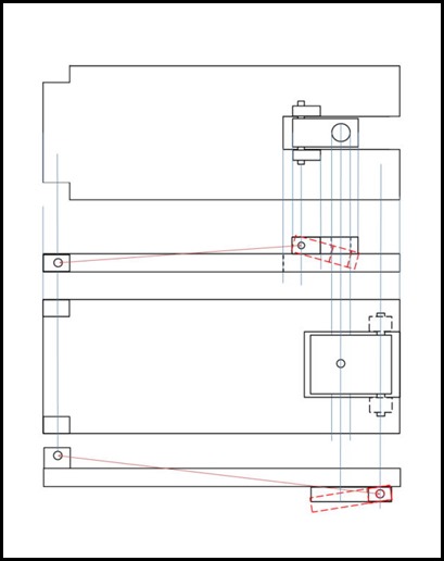
I should now be able to begin fabricating the door itself. I have a piece of 3/4 inch oak for that purpose. The working drawing is below. I will hinge the door on one side and will also hinge both the nut on the top and the motor on the bottom. I believe I have the formulas worked out correctly to compute the step interval to get it to follow the sidereal angle of the earth. I will do some testing after I have the structure built to see how accurate I am. The final proof will of course be in the pictures I take.

drawing

Thursday, November 17, 2016

Barndoor Tracking Mount, Part 1

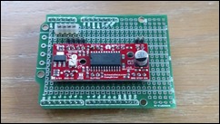
So in my last post, I mentioned I was going to build this DIY equatorial mount for photography and general viewing of the skies. I am using an Arduino UNO board as the controller for the device, which will drive a stepper motor to open and close the “door”. I purchased an EasyDriver card to interface between the Arduino and the stepper motor. I attached it to a shield card I already had for prototyping with the UNO and brought power and motor connections out to pins. The power for the motor and the Arduino will both come from a car starter/air compressor that has a 12VDC auxiliary port. The stepper motor came for the surplus house I mentioned before and is by Oriental Motor in Japan. So far, I have gotten all three parts connected together and have run the motor through some operations that show that I should be able to do the job with it.EasyDriver on shield
I had also obtained a lead screw at the surplus store but have not been able to find a source for a lead screw nut to travel on it. The best source I could find for parts like I want to use for driving the door is parts that are designed for 3D printers. I took a chance and ordered some parts that should be able to work and they should arrive in the next week or two, so I should know how they will work when I write the next installment.

I will probably fabricate the hinging parts for the door since standard hinges may have too much play for the stability I will want. I think I can make some fairly accurate parts in the wood shop we have here, where I can use a drill press to make some nice, tight parts using wood and metal. The base door parts will be made with oak for a nice, hard surface and I have an old, sturdy tripod that should be able to hold the whole apparatus securely.

I have been running some spreadsheets looking at the calculation of the stepping timing for the door to make it match the sidereal angle of the earth. The geometry of the device determines that the speed of the stepping motor needs to vary as the door opens so as to maintain a constant platform. A formula can be easily derived for the stepping frequency and other implementations I have read about have used formulas and tables to minimize the error in the angle. However, I have come to realize that the computational speed of the Arduino processor is fast enough to be able to compute the next step interval well before the interval needs to occur, so accuracy should not be a problem assuming that my formula is correct and that I accurately position the device lined up on Polaris.

Next time I will show you the geometry of the device I am building, the formula I am using to determine the step intervals and, hopefully will know if the hardware I am getting for the stepper will work. Then I can get busy fabricating the platform

Thursday, November 03, 2016

Back Again

It has been a long time since I have posted here. Sorry but life has had other things for me to do. However, I have been playing around with Arduino microcontrollers for a while and have just found a new application.

With the All American Solar Eclipse coming next August 21st, I have started thinking about filming it and have also been interested in filming other astral phenomena so I figure building a polar axis tracker for my camera and telescope needs might be interesting.

I found a design for a DIY Polar Axis Tracker based on the Barn Door design and started looking into the math used to determine how to drive it and the hardware. I was in Portland Oregon this passed Summer and was directed to Surplus Gizmos by my son. They have all kinds of electronic, electric and mechanical hardware for sale.

I was able to get a couple of stepper motors (which may or may not work), a lead screw with an 0.1 inch pitch and a 3/8 inch diameter. These were my first pieces of hardware for the device.

Let me drop back a little and describe the device. A Barn Door Tracker is essentially two pieces of wood with a hinge connecting them. The hinge allows the two parts to swing through an angle as a barn door might when it is opened with respect to the door frame. By anchoring one side of the door to a tripod as a “ground” plane and then moving the other side at a controlled rate, the moving side will remain relatively fixed from a cosmic standpoint as the other side moves through an arc as the earth turns below it.

x

So the trick is to make the “door” open at a rate consistent with the rotation of the earth (360 degrees in 23.9344696 hours). I will be posting the steps I go through here to make this thing work so stay tuned.